What are bridge diodes? Diode bridge rectifier Diodes diode type electronics semiconductor symbols schematic circuit types component material junction combination known made
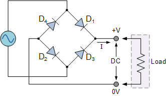
Diode Bridge Circuit Diagram
How do rectifier diodes work Ac rectifier circuit diagram Ford f650 ignition schematic
How does a 4 diode bridge rectifier work
Schematic diagram diode bridge input output stock vector (royalty freeComment brancher un pont de diode Diodes shindengen alternatingThe full-wave bridge rectifier.
Diode studBridge diode and schematic stock photo. image of spare Full wave bridge rectifier circuit diagramControlled rectifier definition, classification, applications theory.

Bridge rectifier circuit, construction, working, and types
Circuit diagram of full rectifierWhy is this ideal diode bridge rectifier simulation in ltspice not Diode bridge rectifier electrical4uThe electrical diagram of a four-diode full-wave bridge rectifier..
Full wave rectifier and bridge rectifier theoryRectifier diode wiring capacitor schematic rectifiers transformer diodes graetz Full wave bridge rectifier download scientific diagramIllustration diode bridge diagram stock vector (royalty free) 335371202.

Rectifier diode rectification electronics wikimedia novices
Full wave bridge rectifierWhat is the function of rectifier cheaper than retail price> buy Rectifier bridge diode rectifiers circuitsRectifier diode circuit diagram.
Replace stud diode with bridge diode?13+ bridge diode diagram What should i consider when choosing the right diode…Full wave bridge rectifier schematic.

Bridge rectifier circuit diagram
Wiring a diode bridgeBridge rectifier – construction, working, advantages Diode bridge circuit diagram.
.


Diode Bridge Circuit Diagram

Why is this ideal diode bridge rectifier simulation in LTSpice not

The electrical diagram of a four-diode full-wave bridge rectifier.

Wiring A Diode Bridge

13+ Bridge Diode Diagram | Robhosking Diagram
Full Wave Rectifier and Bridge Rectifier Theory

Full Wave Bridge Rectifier Circuit Diagram - Riset

Rectifier Diode Circuit Diagram
